ESD Safe Plastic Insert Tray for Electronic Component Packaging
An ESD safe plastic insert tray provides designated positions for sensitive electronic parts inside a larger packaging system. Custom cavities separate components, support approved contact areas, and organize products and accessories within an outer box or container.
WELL CHSIEN PLASTIC CO., LTD. provides custom vacuum forming and thermoformed packaging development in Taiwan. Our product range includes packaging inserts, electronic work trays, antistatic trays, and conductive trays.
For an ESD-related project, “safe” must be supported by defined requirements. Material properties, component fit, handling conditions, and the complete packaging arrangement should be evaluated before the insert is approved.
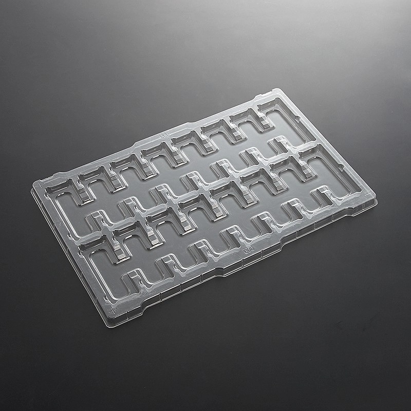 Clear plastic insert tray with two rows of contoured cavities and raised positioning features
Contoured cavities and raised positioning features provide defined placement areas for shaped components. For a custom ESD safe plastic insert tray, WELL CHSIEN can review product contact points, removal clearance, and outer box dimensions together. The selected material must meet the electrical requirements of the intended application.
What Is an ESD Safe Plastic Insert Tray?
A plastic insert tray is a formed inner packaging component designed to fit within an outer package. Unlike a standalone handling tray, its dimensions and support structure must work with both the product and the surrounding box or container.
The insert may hold one product, several identical parts, or a main component with accessories. Individual cavities can maintain orientation and reduce contact between neighboring items.
ESD suitability depends on the selected material and its verified performance in the intended application. A close-fitting cavity alone does not establish electrostatic protection.
Explore our custom packaging inserts for related structural options.
| Packaging element | Main function | What to confirm |
|---|---|---|
| Product cavity | Positions the component | Fit, support, and removal access |
| Accessory pocket | Separates additional items | Clearance from the main product |
| Insert perimeter | Fits within the outer package | Dimensions and movement allowance |
| Support features | Carry the product load | Approved contact locations |
| Cover or upper insert | Helps retain the contents | Clearance above sensitive features |
| Outer packaging | Contains the loaded insert | Mechanical and ESD requirements |
Designing the Insert Around the Product
The starting point is the product’s geometry and contact restrictions.
A component housing may provide a suitable support surface, while exposed terminals, optical surfaces, and soldered features may need clearance. The cavity should locate the product without requiring excessive force during loading or removal.
For example, an electronic module with projecting connectors may need support beneath its housing and recessed spaces around the connectors. If accessories share the package, separate pockets can keep them from contacting the module.
Provide drawings or samples showing:
-
Overall dimensions and tolerances.
-
Approved support surfaces.
-
Areas where contact is prohibited.
-
Projecting features above and below the product.
-
Required loading orientation.
-
Gripping areas for removal.
-
Acceptable movement within the cavity.
Sample approval should use representative products, including relevant dimensional variations.
Matching the Insert to the Outer Box
An insert that fits the product may still perform poorly if it does not fit the outer package.
The design should account for the box’s usable internal dimensions, dimensional variation, closing method, and packing sequence. Excessive clearance may allow the insert to move, while an overly tight fit may make packing difficult or deform the tray.
The outer lid should not transfer unintended pressure to the product.
| Interface requirement | Design question |
|---|---|
| Internal box dimensions | What space is available after the box is assembled? |
| Insert fit | Can the insert be loaded without bending or forcing it? |
| Vertical clearance | Does the closed lid clear the product? |
| Load support | Where does the product weight transfer into the package? |
| Retention | What prevents the contents from leaving their cavities? |
| Unpacking | Can the customer remove the insert and product easily? |
Where several inserts are stacked, define the loaded layer count and the clearance between products. Check the complete packed arrangement rather than the insert alone.
Understanding ESD Material Properties
An ESD safe plastic insert tray should be specified using the properties required by the customer’s ESD control program.
Antistatic generally concerns reduced charge generation. Dissipative and conductive properties concern electrical resistance and charge movement. Discharge shielding is a separate packaging function.
The EOS/ESD Association’s principles of ESD control ↗ explain how packaging properties and handling controls work together.
| Property | Main role | Specification consideration |
|---|---|---|
| Antistatic / low charging | Limits charge generation during contact and separation | Relevant material interactions |
| Dissipative | Provides a controlled resistance path | Required limits and measurement method |
| Conductive | Provides a relatively low-resistance path | Compatibility with the component and process |
| Discharge shielding | Limits external discharge effects | Performance of the complete enclosure |
Color, transparency, and resin type do not establish ESD performance. Request information relevant to the selected material grade and finished application.
Review our antistatic working trays and conductive working trays when discussing electrical requirements.
Material Selection for Custom Inserts
WELL CHSIEN’s vacuum forming materials include PET, PVC, PS, and PP. The availability and suitability of an antistatic, dissipative, or conductive grade should be confirmed for each project.
Material selection must also address rigidity, forming depth, product weight, and operating conditions. The starting sheet thickness alone does not describe the stiffness or material distribution of the finished insert.
| Selection factor | Information needed |
|---|---|
| Mechanical support | Product weight and support locations |
| Electrical performance | Required properties, limits, and test conditions |
| Cavity geometry | Depth, spacing, and product profile |
| Visibility | Whether inspection through the insert is necessary |
| Cleanliness | Particle, residue, and additive restrictions |
| Temperature | Actual storage and operating conditions |
| Service life | Single-use or reusable packaging |
For energized products or components containing batteries, conductive contact needs particular review to avoid unintended electrical connections. Identify exposed contacts during design evaluation.
ESD Shielding and Shipping Protection
An insert is one element of the packaging system.
An open antistatic or conductive insert should not automatically be treated as a discharge-shielding enclosure. When ESD-sensitive products leave an ESD protected area, the complete package may require a suitable shielding bag or enclosure.
If a shielding bag is used, its position within the package should be defined. Confirm that the insert does not pinch, puncture, or place unnecessary stress on the bag during packing and transport.
Likewise, a thermoformed insert is not automatically a cushioning or moisture-barrier system. Evaluate shock protection, vibration, compression, and moisture requirements separately where applicable.
The EOS/ESD Association’s packaging and material handling guidance ↗ provides background on packaging functions inside and outside controlled ESD areas.
Loading, Inspection, and Product Removal
A practical insert supports the work of packing operators and end users.
Finger recesses can provide access to approved gripping areas. Orientation features can help establish loading direction, while separate accessory pockets make the packing arrangement easier to inspect.
Avoid relying on sensitive connectors or components as handles. If the product must be lifted in a particular way, communicate that requirement before the cavity is designed.
For automated handling, submit equipment interface dimensions, gripping requirements, and positioning references. Approval should include trials with the actual equipment where necessary.
See our electronic work trays for related component-handling applications.
Sample Approval and Verification
Sample evaluation should connect mechanical fit, electrical requirements, and outer packaging compatibility.
Before tooling, agree on critical dimensions and acceptance criteria. Electrical specifications should identify the measured property, units, method, and conditioning requirements.
Surface resistance and surface resistivity are different quantities and should not be substituted without explanation.
| Verification item | Approval check |
|---|---|
| Product fit | Loading and removal without excessive force |
| Contact areas | No unintended contact with sensitive features |
| Outer box fit | Practical packing and closing |
| Retention | Product remains in its intended position |
| Loaded clearance | No pressure from covers or upper layers |
| Electrical properties | Results meet the agreed specification |
| Shipping arrangement | Complete package meets the agreed test criteria |
Material data can support selection, but the verification plan should also address the finished insert where appropriate.
Testing scope, sampling frequency, and required reports should be confirmed before production.
Custom Development with WELL CHSIEN
WELL CHSIEN supports custom vacuum forming projects through product evaluation, mold development, sampling, and manufacturing.
Provide the product and outer packaging information together. This allows the insert to be considered as part of the complete package from the beginning.
A typical project review includes:
-
Product drawings, samples, and contact restrictions.
-
Outer box dimensions and packing arrangement.
-
Material and electrical requirements.
-
Cavity layout and tooling feasibility.
-
Sample evaluation and required verification.
-
Approval of drawings, materials, and packing instructions.
-
Production according to the agreed specification.
Learn more about our vacuum formed products and product packaging range.
FAQ: ESD Safe Plastic Insert Tray
1. How is an insert tray different from a standalone tray?
An insert is designed to fit within another package. Its dimensions, support features, and retention arrangement must work with the outer box as well as the product.
2. Does an ordinary plastic insert provide ESD protection?
Not automatically. The selected material must have properties suitable for the application, supported by agreed verification.
3. Which material should I choose?
Select the grade using your electrical requirements, product geometry, weight, and service conditions. A base resin name alone is not a complete specification.
4. Can the insert hold a product and accessories?
Separate cavities can be evaluated for each item. Provide the dimensions, loading arrangement, and restrictions on contact between contents.
5. Can an insert prevent shipping damage?
It can provide positioning and separation, but protection depends on the complete package. Evaluate the loaded insert, retention method, cushioning, and outer carton together.
6. Does a conductive insert eliminate the need for shielding packaging?
No. Conductivity and discharge shielding describe different functions. Confirm the complete packaging requirements for the product’s handling route.
7. Can a transparent insert be ESD suitable?
Potentially, depending on the available grade and required performance. Transparency does not establish electrical suitability.
8. Can inserts be reused?
Reuse depends on physical condition, cleanliness, and continuing electrical performance. Define inspection and replacement criteria for the intended use.
9. What should be checked if the outer box changes?
Review internal dimensions, lid clearance, insert movement, packing access, and any effect on the shielding arrangement. A box change may require sample approval.
10. What information is needed for a quotation?
Provide product drawings or samples, outer box dimensions, cavity quantity, electrical specifications, order quantity, and delivery requirements. Include required inspection records and transport testing.
Request an ESD Insert Tray Review
WELL CHSIEN provides custom thermoformed inserts for electronic and industrial packaging applications.
Send your product drawings, samples, and outer packaging dimensions to discuss cavity design, material options, tooling, and production requirements. MOQ, sample timing, and lead time can be confirmed for the agreed project.
Contact WELL CHSIEN to discuss your ESD safe plastic insert tray requirements.
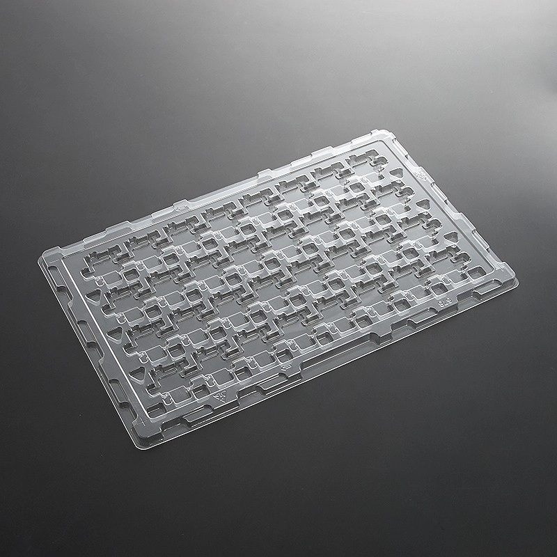 Clear thermoformed insert tray with a dense grid of small shaped cavities and a raised perimeter
This closely spaced cavity layout keeps small parts individually organized for counting, inspection, and packing. Cavity spacing can be evaluated to balance packing density with loading access. Custom development also considers the fit between the insert and outer packaging, alongside the specified ESD material properties.
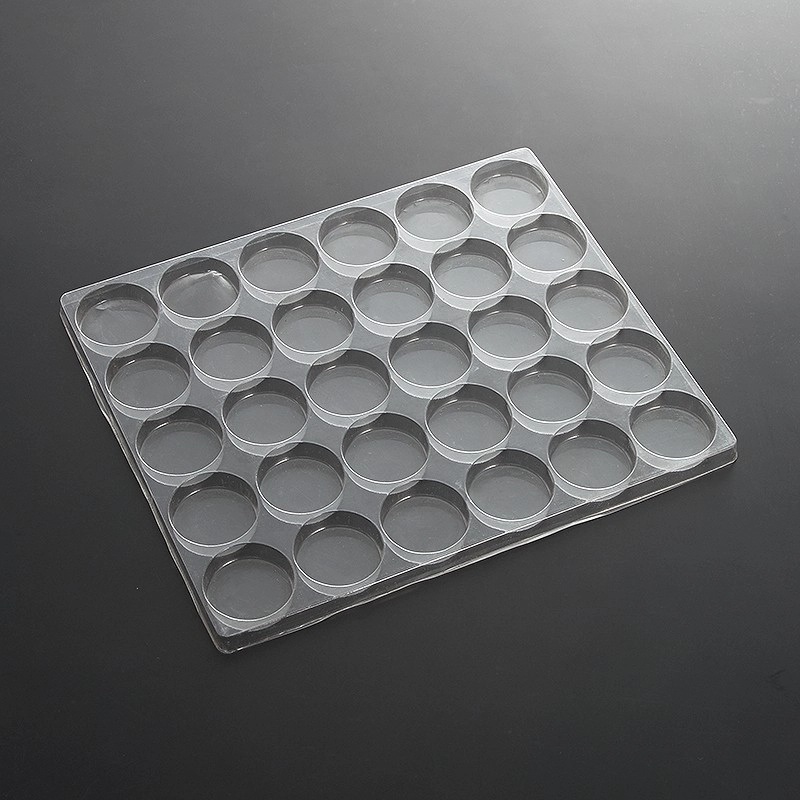 Clear rectangular plastic insert tray with evenly arranged circular pockets and raised separating walls
Individual circular pockets provide separate positions for round components. Pocket diameter, depth, and clearance can be reviewed against product samples to support practical loading and removal. For ESD safe plastic insert tray applications, material performance and compatibility with the complete packaging system should be confirmed before approval.
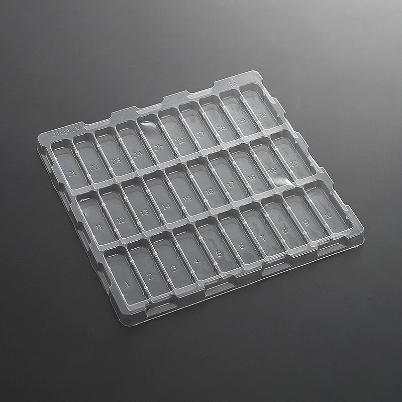 Clear plastic insert tray with 30 numbered rectangular cavities arranged in three rows
Thirty numbered cavities help identify individual positions during loading, counting, and inspection. The rectangular pockets keep parts separated in a consistent arrangement. WELL CHSIEN can discuss cavity dimensions, position markings, and outer package fit for custom ESD safe plastic insert tray projects.